Definition – computer controlled movement of a tool through space
Computer controlled – local processor on the machine tool
Movement – following Cartesian (2D/3D) coordinates defined by the source code
Tool – predominately visualised with a milling cutter but could be anything from a glue gun to a plasma torch
Space – the machine tool envelope – the XYZ motion limits
Component Definition
CAD model or engineering drawing. A simple component defined in an engineering drawing could be taken straight to the machine but consider the dimensions – are they appropriate for the direct definition of tool motions in standard cycles on your controller? Tool radius compensation is usually handled by the controller software when using shop floor software.
Source code – a list of commands listed in a Program defining machine actions and tool movements, the program will either originate from CAM software following a CAD model or from shop floor software.
G-Code or ISO (6983) Wiki
This is the fundamental machine control code, it can be manually input or output from a CAM system via a translator called a Post Processor. There are three broad elements in this language – machine control M codes, motion control G codes and the position coordinates. Complex 3D forms will generally be machines using ISO output from a CAM system.
Conversational Programming
For simpler components programmed at the machine conversational programming (CP) can be used. This system of automating common tasks such as machining a pocket or drilling a group of holes though a canned cycle (similar to a wizard or macro) can make significant time saving hiding or bypassing the G-code. CP languages and protocol are unique to individual manufacturers, the code above is from a Heidenhain controller.
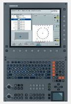
Controller – the user interface of the machine tool. Although they facilitate a lot of common functions, the machine control interfaces are very different in layout and workflow. You will commonly see a small number of controllers fitted to many different CNC machines.
Common controller manufacturers are Haas, Mazak, Heidenhain, Hurco, Fanuc and Prototrak
Offsets
When the machine tool is first started all the drive axis are ‘homed’ – driven to their limits to determine the actual position of the centre and end of the spindle in the machine envelope. This defines the the machine coordinate system.
But the range of tools used in a job will have different lengths and the component geometry is relative to a position within its extents – this is where Offsets come in, constantly adjusting the XYZ reference point relative to fixture positions and tool changes.
Detailed discussion in Offsets
Cost of a crash
Ultimately the machine drives will simply do what they’re told – although we have virtual collision checking there is no physical collision avoidance, crashing a tool costs time and money so use all your resources and training to prove your code before cutting material.
Common MC workflow
- Machine checks – power, oil levels, general mechanical
- Power on
- Home all axis
- Load tools
- Set Tool Offset
- Set work/fixture offsets
- Load program
- Check program
- Run program
- Check component
- Adjust offsets
Resources
HSMWorks
Heidenhain TNC Training
CNCCookbook
Conversational Programming discussion
Simulators and offline programming
MazCAM
Heidenhain iTNC
CNC Simulator
ShopTurn
ShopMill


